Table of Contents
Introduction: The Fascinating Physics That Drives Missiles

When a missile launches into the sky, it carries no magic. It obeys every natural law written into the fabric of the universe. Thrust fights gravity. Drag slows momentum. Control surfaces adjust angles based on feedback loops running thousands of times per second. What seems like a weapon of war is actually a traveling classroom in motion, demonstrating Newton’s principles and energy conservation in real time.
Missiles prove that physics rules everything. Their flight paths form perfect parabolas dictated by gravitational acceleration. Their speed depends on how efficiently they convert chemical bonds into kinetic energy. Even their stability comes from aerodynamic principles that govern birds and aircraft alike. Understanding missiles means understanding how nature’s equations govern motion, force, and energy.
Every missile type follows these same fundamental laws. The differences lie in how they apply them. A cruise missile hugs terrain using lift and drag. A ballistic missile arcs through space where air resistance disappears. An interceptor missile calculates intercept angles using real-time vector mathematics. But all of them obey physics without exception.
The engineering marvel is not that missiles defy nature. The marvel is how precisely they harness it.
Types of Missiles and Their Physical Operating Principles
| Missile Type | Core Physical Principle |
|---|---|
| Ballistic missiles | Follow parabolic trajectories governed by gravity and initial velocity after powered flight ends |
| Cruise missiles | Maintain constant altitude using aerodynamic lift balanced against weight and drag forces |
| Hypersonic missiles / glide vehicles | Manage extreme thermal loads from air compression at speeds exceeding Mach 5 |
| Anti-ship missiles (AShM) | Navigate sea-skimming flight paths using ground effect to reduce radar detection |
| Surface-to-air missiles (SAM) | Calculate intercept geometry using predictive algorithms and pursuit curves |
| Air-to-air missiles (AAM) | Execute high-G turns using thrust vectoring and control surface deflection |
| Anti-radar / anti-radiation missiles (ARM) | Follow electromagnetic radiation gradients to locate and track emission sources |
| Anti-tank guided missiles (ATGM) | Use shaped charge physics to concentrate explosive energy into penetrating jets |
| Anti-ballistic / interceptor missiles (ABM) | Achieve hit-to-kill accuracy through precise timing and relative velocity calculations |
| Anti-satellite missiles | Reach orbital velocities and altitudes where atmospheric drag becomes negligible |
1. How Missiles Use Newton’s Laws to Begin Their Journey
Isaac Newton gave us three laws that describe all motion. Missiles follow every one of them from ignition to impact. The first law states that objects resist changes in motion. Missiles sitting on a launch rail stay there until a force acts on them. That force comes from burning propellant, which creates expanding gases that push outward in all directions.
The second law connects force, mass, and acceleration. When hot gases rush out of the nozzle, they generate thrust proportional to the mass flow rate and exit velocity. A heavier missile needs more thrust to achieve the same acceleration. Engineers calculate these relationships precisely, knowing that doubling the thrust doubles the acceleration if mass stays constant.
The third law makes rockets possible. “For every action, there is an equal and opposite reaction.” Gases shooting backward create forward thrust. This principle works in space where there is nothing to push against. The missile does not need air or ground contact. It pushes against its own expelled mass.
During launch, thrust must overcome both weight and initial inertia. The missile accelerates as propellant burns away, reducing mass while thrust remains relatively constant. This creates increasing acceleration throughout the burn phase. Guidance systems monitor this acceleration using sensors that detect even tiny deviations from the planned trajectory.
Control surfaces and thrust vectoring allow course corrections. Small adjustments in thrust direction or surface angle create forces that rotate the missile. These corrections happen continuously, balancing aerodynamic forces with propulsive forces to maintain the desired path. Every adjustment follows Newton’s laws exactly.
The transition from stationary to supersonic happens in seconds for many missiles. This rapid acceleration demands precise engineering. Too much structural stress causes failure. Too little thrust means the missile cannot reach its target. The balance comes from understanding how forces interact with mass and motion.
Newton’s Laws Applied to Missile Launch Phases
| Launch Phase Element | Newtonian Physics Application |
|---|---|
| Ignition sequence | Chemical reaction generates high-pressure gases that create unbalanced forces on the missile |
| Initial acceleration | Net force equals mass times acceleration, with thrust force minus drag and weight forces |
| Propellant burn | Decreasing mass causes acceleration to increase even as thrust remains relatively constant |
| Thrust vectoring | Gimbal angles redirect momentum vector by changing the direction of expelled mass |
| Inertial resistance | Missile’s mass resists directional changes, requiring continuous corrective forces |
| Velocity increase | Acceleration integrated over time produces velocity following kinematic equations |
| Separation staging | Discarding spent rocket stages reduces mass and increases acceleration efficiency |
| Momentum conservation | Total system momentum remains constant in the absence of external forces |
2. How Missiles Balance Gravity and Drag in Mid-Air
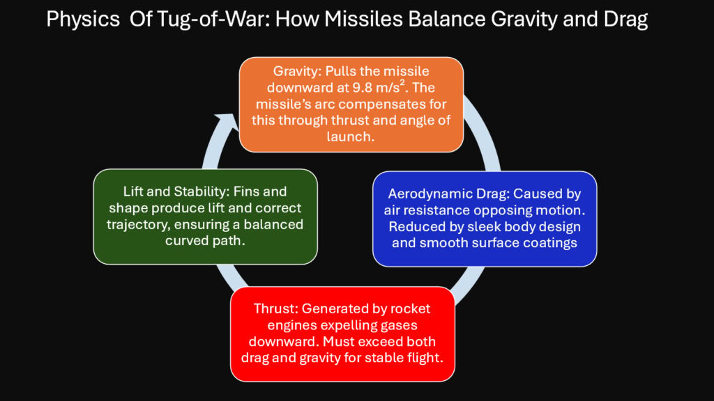
Gravity never stops pulling. From launch to impact, Earth’s gravitational field applies a constant downward acceleration of approximately 9.8 meters per second squared. Missiles must account for this force in every trajectory calculation. A ballistic missile fired horizontally would still fall toward the ground, creating a curved path combining forward motion with downward acceleration.
Drag opposes motion through air. As a missile moves, it collides with air molecules that resist its passage. This resistance depends on velocity squared, meaning that doubling speed quadruples drag force. The drag equation includes air density, velocity, reference area, and a drag coefficient that describes how streamlined the shape is.
Engineers shape missiles to minimize drag coefficients. Pointed nose cones split air smoothly. Streamlined bodies reduce turbulent wake formation. Fins and control surfaces are designed to produce control forces while adding minimal drag. Wind tunnel testing reveals how different shapes interact with airflow at various speeds.
The flight path results from continuous interplay between thrust, gravity, and drag. A cruise missile maintains level flight by generating enough thrust to balance drag while wings create lift to balance weight. A ballistic missile coasts after its propellant burns out, following a parabolic arc where only gravity and drag influence motion.
At higher altitudes, air density decreases exponentially. This reduces drag but also reduces lift for missiles using aerodynamic control. Ballistic missiles that exit the atmosphere experience near-zero drag in space, then encounter increasing drag during reentry. The changing conditions require different control strategies for different flight phases.
Terminal velocity occurs when drag force equals gravitational force for a falling object. Missiles under power can exceed this limit because thrust adds to the equation. Without thrust, a missile’s maximum speed is limited by how much drag force the structure can generate while falling.
Calculating trajectory requires solving differential equations that account for changing conditions. Gravity remains constant, but drag changes with altitude, velocity, and even air temperature. Modern guidance computers solve these equations thousands of times per second, adjusting the flight path to compensate for real conditions versus predicted conditions.
Gravitational and Drag Forces During Missile Flight
| Force Factor | Physical Effect on Trajectory |
|---|---|
| Gravitational acceleration | Constant 9.8 m/s² downward force creates parabolic flight paths for unpowered flight segments |
| Air density variation | Exponential decrease with altitude changes drag force and aerodynamic control effectiveness |
| Drag coefficient | Streamlined missile shapes achieve values between 0.15 and 0.5 depending on design |
| Velocity dependence | Drag force increases with velocity squared, creating nonlinear resistance effects |
| Cross-sectional area | Larger frontal areas experience greater drag force for the same speed and air density |
| Altitude compensation | Trajectory calculations adjust for changing atmospheric conditions throughout flight |
| Terminal velocity limits | Maximum unpowered speed where drag force equals weight force |
| Reentry heating | Kinetic energy converts to thermal energy through atmospheric friction during descent |
3. How Missiles Transform Energy for Precision and Power
Missile propulsion relies on the principles of chemistry. Chemical energy stored in propellant molecules converts to thermal energy through combustion, then to kinetic energy as gases accelerate out of the nozzle, and finally to the missile’s kinetic energy as it gains speed.
The efficiency of this conversion determines missile performance. Solid rocket motors achieve efficiencies around 60 to 70 percent, with losses occurring as heat that radiates away or conducts into the motor casing. Liquid engines can reach slightly higher efficiencies through better combustion control and optimized expansion ratios in the nozzle.
Specific impulse measures how effectively a propulsion system uses propellant. It represents the thrust produced per unit of propellant weight per second. Higher specific impulse means more energy extraction from each kilogram of fuel. This parameter directly affects range because it determines how much velocity change a given propellant mass can provide.
Kinetic energy equals one-half mass times velocity squared. This relationship means that doubling velocity requires four times the energy. Missiles seeking high speeds must dedicate substantial propellant mass to reach those velocities. The exponential nature of the rocket equation compounds this challenge, as carrying more propellant increases mass, which requires more energy to accelerate.
Thermal energy management becomes critical at high speeds. Air compression ahead of a hypersonic missile generates temperatures exceeding thousands of degrees. This thermal energy comes from the missile’s kinetic energy through friction and compression. Materials must withstand these temperatures without melting or losing structural integrity.
Potential energy plays a role in ballistic trajectories. A missile climbing to high altitude converts kinetic energy to gravitational potential energy. During descent, this potential energy converts back to kinetic energy, increasing speed. The total energy minus losses to drag remains constant throughout the flight.
Guidance systems consume electrical energy to operate sensors, computers, and control actuators. This energy comes from batteries or generators powered by the propulsion system. Energy budgets must account for all systems to ensure power remains available throughout the mission duration.
Energy equations allow precise predictions of missile behavior. Knowing initial energy, propellant properties, and loss mechanisms enables calculation of achievable velocity, range, and altitude. These calculations form the foundation of missile design and mission planning.
Energy Transformations in Missile Propulsion Systems
| Energy Transformation Stage | Physical Process and Efficiency |
|---|---|
| Chemical bond energy | Propellant molecules store energy in molecular bonds released during combustion |
| Combustion chamber heating | Chemical reactions convert bond energy to thermal energy at temperatures exceeding 3000 K |
| Gas expansion work | Hot gases expand through nozzle, converting thermal energy to directed kinetic energy |
| Thrust generation efficiency | Solid motors achieve 60-70% efficiency, liquid engines reach 65-75% in optimal conditions |
| Missile acceleration | Expelled gas momentum transfers to missile body, increasing kinetic energy |
| Aerodynamic heating | Friction converts kinetic energy to thermal energy, especially during hypersonic flight |
| Potential energy storage | Climbing missiles convert kinetic energy to gravitational potential energy |
| Electrical power systems | Chemical or mechanical energy converts to electrical energy for guidance computers |
4. How Missiles Apply Control Theory for Real-Time Correction
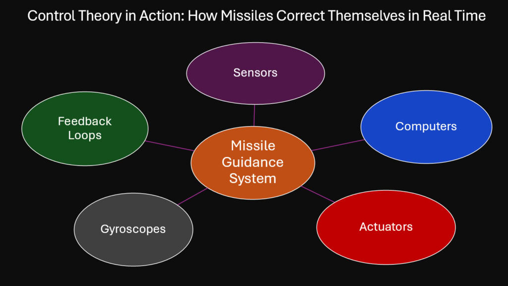
A missile cannot simply point and fly. Wind gusts deflect it. Manufacturing imperfections create slight imbalances. Targets move. Real-time correction transforms a guided missile from an uncontrolled rocket into a precision instrument. Control theory provides the mathematical framework that makes this possible.
Feedback loops form the core of missile guidance. Sensors measure current position, velocity, and orientation. Computers compare these measurements to desired values. The difference, called error, drives corrective actions. Control surfaces adjust angles or thrust vectoring changes direction to reduce error.
Proportional-integral-derivative controllers, known as PID controllers, dominate missile guidance systems. The proportional term responds to current error magnitude. The integral term accounts for accumulated past error. The derivative term predicts future error based on rate of change. Combining these three terms creates smooth, stable corrections.
Gyroscopes measure rotational rates around three axes. These spinning masses resist changes in orientation through conservation of angular momentum. Modern missiles use ring laser gyroscopes or fiber-optic gyroscopes that have no moving parts but measure rotation through optical interference patterns. The precision reaches fractions of a degree per hour.
Accelerometers detect linear acceleration along each axis. By integrating acceleration over time, guidance computers calculate velocity changes. Integrating velocity gives position changes. This inertial navigation works without external references, though errors accumulate over time and require correction from other sensors.
Global positioning satellites provide position updates that correct inertial navigation drift. Radar seekers measure target range and angle. Infrared sensors track heat signatures. Each sensor type has strengths and weaknesses, and modern missiles often combine multiple sensor types for robust guidance.
Update rates matter critically. A guidance computer running at 100 hertz makes corrections every 10 milliseconds. Faster rates allow quicker response to disturbances but require more computational power. The update frequency must exceed the frequency of disturbances to maintain stability.
Kalman filters combine multiple sensor inputs mathematically. They weight each sensor based on its accuracy and integrate the data to produce optimal state estimates. This filtering reduces noise and improves tracking accuracy, allowing missiles to follow complex paths with minimal error.
Control Systems and Sensors for Missile Guidance
| Control System Component | Function and Physical Principle |
|---|---|
| Ring laser gyroscopes | Detect rotation using Sagnac effect where laser beams travel different distances in rotating frames |
| MEMS accelerometers | Measure acceleration through microscopic proof mass deflection detected capacitively |
| GPS receivers | Calculate position from time delays in signals from multiple satellites |
| Inertial measurement units | Integrate acceleration data to track velocity and position changes over time |
| PID control algorithms | Generate correction commands proportional to error, error integral, and error derivative |
| Kalman filtering | Optimally combine noisy sensor measurements using statistical estimation theory |
| Control surface actuators | Convert electrical commands to mechanical deflections using hydraulic or electric motors |
| Update rate requirements | Guidance computers run at 50-200 Hz to respond faster than disturbance frequencies |
5. How Missiles Rely on Aerodynamics to Stay Stable and Fast
Air shapes missile behavior as powerfully as engines do. Aerodynamic forces determine whether a missile flies straight or tumbles. They control how much energy reaches the target versus dissipating as heat and turbulence. Understanding airflow patterns separates successful designs from failures.
Lift generation follows the same principles for missiles as for aircraft. Angled surfaces deflect air downward, and Newton’s third law creates an upward reaction force. Wings on cruise missiles provide lift to offset weight, enabling sustained flight without constant thrust. Control fins generate lift forces that rotate the missile for steering.
The center of pressure represents where aerodynamic forces act on the missile body. For stable flight, this point must lie behind the center of mass. This arrangement creates a restoring moment when the missile angles off course, naturally returning it to straight flight. Unstable configurations require continuous active control to prevent tumbling.
Boundary layer behavior affects drag significantly. Air molecules directly touching the missile surface stick to it, creating a layer of slower-moving air. This boundary layer can remain smooth and laminar or transition to turbulent chaotic flow. Turbulent boundary layers increase drag but can prevent flow separation that causes even worse drag increases.
Shock waves form when missiles exceed the speed of sound. The air cannot move aside fast enough, creating compression waves that propagate at sound speed. These shock waves increase drag dramatically and generate intense heating. Missile shapes minimize shock strength through careful contouring of nose cones and body transitions.
Mach number, the ratio of missile speed to sound speed, determines flow regime. Subsonic flight below Mach 0.8 features relatively simple aerodynamics. Transonic flight between Mach 0.8 and 1.2 creates complex mixed flow patterns. Supersonic flight above Mach 1.2 and hypersonic flight above Mach 5 each present distinct challenges requiring specialized design approaches.
Wind tunnel testing reveals aerodynamic characteristics before flight tests. Scale models fly in controlled airstreams while sensors measure forces and moments. Flow visualization using smoke or pressure-sensitive paint shows where air separates or shock waves form. This empirical data validates computer simulations and guides design refinements.
Computational fluid dynamics simulates airflow by solving the Navier-Stokes equations numerically. These equations capture conservation of mass, momentum, and energy in flowing fluids. Modern supercomputers can model complex three-dimensional flows, though hypersonic simulations still challenge even the fastest processors.
Aerodynamic Principles Governing Missile Flight
| Aerodynamic Factor | Effect on Missile Performance |
|---|---|
| Lift-to-drag ratio | Determines flight efficiency with typical values from 3 to 15 depending on design |
| Center of pressure location | Must be aft of center of mass by 1-3 calibers for passive stability |
| Boundary layer transition | Turbulent flow increases skin friction drag but improves control surface effectiveness |
| Shock wave formation | Occurs at supersonic speeds, creating wave drag that increases rapidly above Mach 1 |
| Body fineness ratio | Length-to-diameter ratios of 10-15 optimize drag reduction for supersonic missiles |
| Control surface sizing | Fins sized to generate sufficient control moments without excessive drag penalties |
| Base drag contribution | Blunt rear ends create low-pressure wake zones accounting for 30-50% of total drag |
| Reynolds number scaling | Affects boundary layer behavior and wind tunnel test correlation to full-scale flight |
6. How Missiles Showcase the Perfect Harmony of Mathematics and Physics
Every missile trajectory exists first as equations before becoming reality. Mathematical models predict where the missile will go. Physics determines whether those predictions match actual flight. The convergence of calculation and natural law creates the precision that defines modern guided missiles.
Vector mathematics describes missile motion in three-dimensional space. Position, velocity, and acceleration are vectors with magnitude and direction. Adding vectors follows geometric rules that combine components. Guidance computers perform these vector operations continuously, tracking how forces change motion state.
Differential equations govern dynamic systems like missiles. These equations relate rates of change to current conditions. Solving them predicts future states from present conditions. Newton’s second law itself forms a second-order differential equation connecting force to acceleration and position.
Numerical integration methods approximate solutions when analytical solutions are impossible. The Runge-Kutta method and similar algorithms step forward in small time increments, calculating how conditions change at each step. Accuracy depends on step size, with smaller steps providing better approximation at the cost of more computation.
Intercept geometry requires solving pursuit curves. If the missile flies directly toward where the target is now, it will miss because the target moves during flight. Lead pursuit aims ahead of the current target position. Proportional navigation, used by most modern missiles, maintains a constant bearing rate to the target, naturally achieving efficient intercept.
Kalman filtering, mentioned earlier for sensor fusion, exemplifies mathematical sophistication in missile systems. The algorithm uses matrix mathematics and probability theory to optimally estimate system states from noisy measurements. It predicts forward using dynamics models, then updates estimates when new measurements arrive.
Optimal control theory determines the best trajectory to minimize fuel consumption or flight time. The calculus of variations provides mathematical tools to solve these optimization problems. The resulting solutions often reveal counterintuitive strategies that outperform intuitive approaches.
Monte Carlo simulations test missile performance across thousands of scenarios with varying conditions. Random variations in wind, target motion, and system parameters create a statistical distribution of outcomes. This analysis quantifies reliability and identifies weaknesses before real-world deployment.
Mathematical Methods in Missile Guidance and Trajectory Calculation
| Mathematical Technique | Application in Missile Systems |
|---|---|
| Vector calculus | Describes position, velocity, and acceleration in three-dimensional space |
| Differential equations | Models force-motion relationships and predicts future states from current conditions |
| Runge-Kutta integration | Numerically solves trajectory equations with fourth-order accuracy in small time steps |
| Proportional navigation | Maintains constant line-of-sight rotation rate to achieve efficient intercept geometry |
| Matrix operations | Transforms coordinate systems and processes multi-sensor data in guidance algorithms |
| Kalman filtering | Combines predicted states with measurements using optimal statistical weighting |
| Optimization algorithms | Calculates minimum-time or minimum-fuel trajectories subject to physical constraints |
| Monte Carlo analysis | Simulates thousands of flight scenarios to assess performance reliability statistics |
Conclusion: Why Missiles Prove Physics Is the True Power Behind Precision
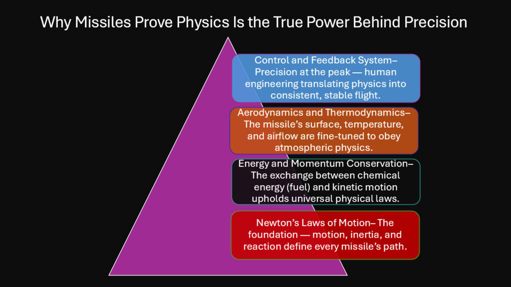
Missiles submit to nature completely. They cannot violate conservation of energy. They cannot ignore gravity or friction. They cannot accelerate without pushing against something. Every successful flight represents physics working exactly as the equations predict.
The beauty lies in the harmony. Thrust overcomes drag while guidance systems correct for wind. Energy transforms from chemical to kinetic with calculable efficiency. Sensors measure motion, computers calculate corrections, and actuators apply forces according to feedback control laws. Each component plays its role in a system governed entirely by natural principles.
Missiles teach us that precision comes from understanding, not from force. The most powerful rocket cannot overcome poor aerodynamics. The fastest computer cannot compensate for unstable design. Success requires matching engineering decisions to physical reality at every level.
Human ingenuity shows in how we harness these laws rather than fight them. We shape nose cones to minimize shock waves. We design guidance algorithms that exploit pursuit geometry. We select materials that survive thermal loads. But we never change the underlying physics.
Future developments will push boundaries further. Hypersonic missiles will manage plasma sheaths that disrupt communications. Electromagnetic railguns will launch projectiles using Lorentz forces instead of combustion. Directed energy weapons will deliver power at light speed. Yet even these advances will obey the same fundamental laws.
Key Physics Principles Demonstrated Throughout Missile Flight
| Physical Principle | Demonstration in Missile Operation |
|---|---|
| Conservation of momentum | Exhaust gases expelled backward produce equal forward momentum in missile body |
| Conservation of energy | Total energy remains constant as it transforms between chemical, kinetic, thermal, and potential forms |
| Newton’s second law | Acceleration equals net force divided by mass at every instant throughout flight |
| Gravitational attraction | Constant downward acceleration creates parabolic trajectories for ballistic flight segments |
| Aerodynamic drag | Velocity-squared resistance force opposes motion and generates heat through friction |
| Angular momentum conservation | Gyroscopes maintain reference orientation through resistance to rotational changes |
| Feedback control stability | Negative feedback loops correct deviations and maintain desired flight path |
| Mathematical predictability | Differential equations accurately predict motion when initial conditions and forces are known |