Table of Contents
Introduction: Robotic Sensors and the Foundation of Robot Sensing
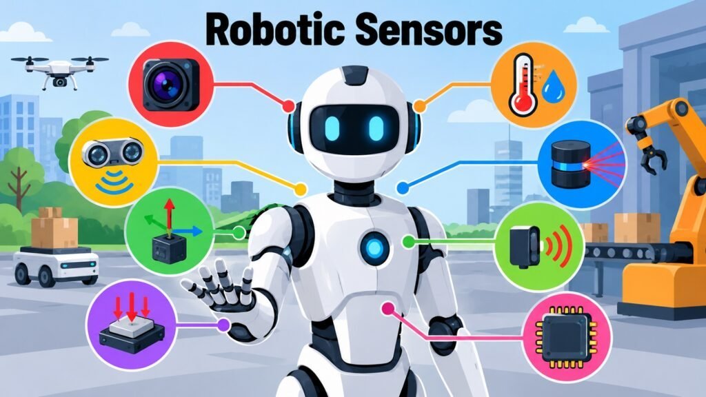
Robotic Sensors are important aspects of Robotics, and understanding them is central to understanding how robots interact with the physical world. A robot without sensors cannot detect distance, measure force, track motion, or respond to environmental change. Sensors form the measurement layer that connects physical phenomena with computational systems, converting continuous physical reality into discrete data. Without that layer, autonomous operation is impossible.
Sensing must be distinguished from the other functions that make up a robotic system. Sensing refers to detecting and measuring physical quantities from the environment or from within the robot itself. Perception interprets those measurements. Intelligence makes decisions on interpreted information. Control generates actuator commands, and actuation carries them out. Robotic Sensors sit at the start of this chain, and their measurement quality influences everything that follows.
A genuine understanding of Robotic Sensors requires more than knowing sensor names. It requires knowing the physical principle each type relies on, the characteristics that determine measurement quality, and the limitations that constrain usefulness in real conditions. Accuracy, precision, resolution, sensitivity, drift, noise, and repeatability are not abstract concerns. They determine whether a robot performs its task reliably. Calibration and measurement reliability belong to any serious discussion of sensing for exactly this reason.
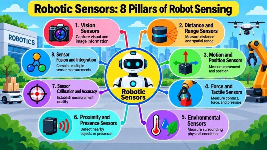
This article develops a structured framework across eight interconnected aspects. It begins with the major sensor categories: vision sensors, distance and range sensors, motion and position sensors, force and tactile sensors, environmental sensors, and proximity and presence sensors. It then addresses measurement quality through calibration and accuracy, and closes with sensor fusion and integration, which describes how multiple sensing technologies can be combined to produce information that is more complete and more reliable than any single sensor can provide alone.
Table 1: Robotic Sensors — Overview of the Eight Foundational Aspects
| Aspect | Primary Focus |
| Vision Sensors | Converting visual phenomena into measurable image or depth data |
| Distance and Range Sensors | Measuring spatial separation between sensor and target |
| Motion and Position Sensors | Detecting movement, orientation, displacement, and acceleration |
| Force and Tactile Sensors | Measuring contact forces, torques, pressure, and surface interaction |
| Environmental Sensors | Detecting atmospheric, chemical, thermal, and acoustic conditions |
| Proximity and Presence Sensors | Detecting whether an object or surface is within a defined zone |
| Sensor Calibration and Accuracy | Quantifying and correcting measurement quality over time |
| Sensor Fusion and Integration | Combining multiple sensor outputs for more complete measurements |
1. Robotic Sensors: Vision Sensors
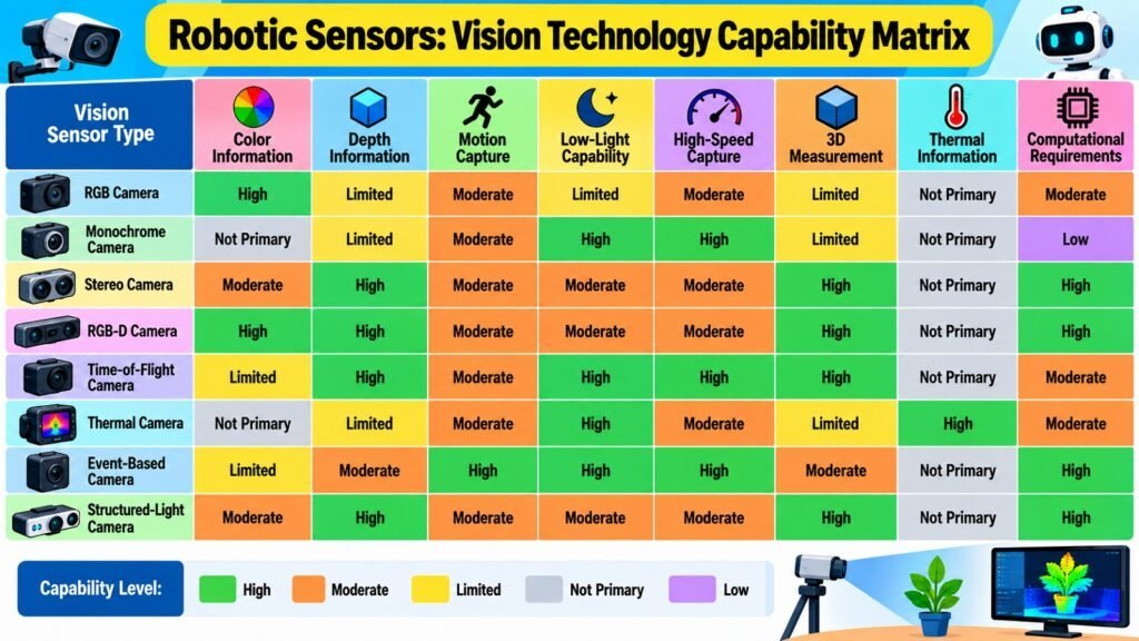
Vision Sensors are among the most information-rich Robotic Sensors available. Their role is to convert visual phenomena into structured data that robotic systems can use. The fundamental operating principle is image formation: light from a scene is focused through an optical system onto a detector array, which converts it into electrical signals and then into digital values. What gets captured depends on the sensor’s spectral range, its spatial resolution, and the characteristics of the optical system in front of it.
RGB cameras capture reflected visible light across three color channels and are widely used in robot vision. Monochrome cameras, which measure intensity without color differentiation, offer higher sensitivity and suit low-light conditions better. Stereo cameras use two spatially separated lenses to calculate depth from disparity, which is the horizontal pixel difference between matching features in the two images. The accuracy of that depth calculation depends on the baseline distance and the resolution at which disparity is measured.
Depth cameras take a more direct approach. Structured light sensors project a known pattern and measure how it deforms on a surface to infer depth. Time-of-flight sensors measure how long emitted light takes to return from a surface and convert that interval to distance, generating depth maps without disparity computation. Thermal cameras respond to infrared radiation rather than visible light, which suits them to situations where surface temperature is the measurement of interest. Event-based cameras generate signals only when individual pixels detect a brightness change, giving very high temporal resolution at low power.
Lighting conditions, motion blur, reflective or absorptive surfaces, and outdoor illumination variability all affect vision sensor performance. Field of view, frame rate, and focal length determine how much of a scene is captured and how reliably fast events are recorded. No single vision technology performs well under all conditions, and evaluating a sensor means understanding these trade-offs honestly.
Table 2: Robotic Sensors — Vision Sensor Technologies and Primary Sensing Characteristic
| Vision Sensor Type | Primary Sensing Characteristic |
| RGB camera | Captures reflected visible light in three color channels |
| Monochrome camera | Measures luminance intensity with higher sensitivity than RGB |
| Stereo camera | Derives depth from pixel disparity between two spatially offset lenses |
| Structured light depth camera | Infers depth by measuring deformation of a projected pattern |
| Time-of-flight depth camera | Calculates range by measuring round-trip time of emitted light |
| Thermal infrared camera | Measures emitted infrared radiation to detect surface temperature variation |
| Event-based camera | Generates signals per pixel only on brightness change events |
| Wide-angle fisheye camera | Covers very wide field of view with geometric distortion at edges |
2. Robotic Sensors: Distance and Range Sensors
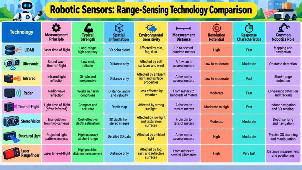
Distance and Range Sensors are Robotic Sensors that measure the spatial separation between a robot and an external object, surface, or feature. The result may seem straightforward, but the methods used to obtain it vary widely, and each brings a different combination of range, accuracy, resolution, and sensitivity to environmental conditions.
LiDAR emits laser pulses and measures the time before a reflected return is received. Since the speed of light is constant and known, distance follows from travel time. LiDAR achieves high angular resolution and can operate over long distances, but its performance drops in heavy rain, fog, or snow, because airborne particles scatter the beam. Ultrasonic sensors operate on the same principle using sound waves rather than light. They are less expensive and reliable across varied surface materials, but their angular resolution is poor and the speed of sound varies with temperature and air turbulence, which introduces measurement uncertainty.
Radar uses radio waves, which penetrate precipitation far more effectively than laser light, making it robust in outdoor conditions where LiDAR degrades. Spatial resolution is lower, but range is typically long. Time-of-flight sensors in a compact form use near-infrared light and phase-shift measurement rather than pulse timing. They are practical for indoor short-to-medium ranges but can suffer from strong ambient light interference. Infrared triangulation sensors measure the angle at which reflected light returns to determine distance and work well over short ranges at low cost.
Surface properties have significant influence on range sensor performance. Dark or matte surfaces absorb laser energy and can cause missed returns. Specular surfaces deflect beams rather than reflecting them back toward the sensor. Small or thin targets may return a weak signal regardless of which technology is used. Keeping range sensing distinct from object interpretation is also important: a range sensor answers how far, not what is there.
Table 3: Robotic Sensors — Range Sensing Technologies and Key Measurement Characteristics
| Range Sensing Technology | Key Measurement Characteristic |
| LiDAR | High angular resolution using pulsed laser light; degrades in precipitation |
| Ultrasonic | Sound-wave ranging; reliable on varied surfaces but limited angular resolution |
| Radar | Radio-wave ranging with strong weather penetration and long range |
| Time-of-flight (phase-shift) | Compact near-infrared ranging for short to medium indoor distances |
| Stereo vision depth | Passive range estimation from image disparity; requires scene texture |
| Structured light | Active depth measurement using projected patterns; suited to indoor use |
| Infrared triangulation | Short-range proximity ranging using the angle of infrared return |
| Single-point laser rangefinder | High-accuracy distance measurement along a single line of sight |
3. Robotic Sensors: Motion and Position Sensors
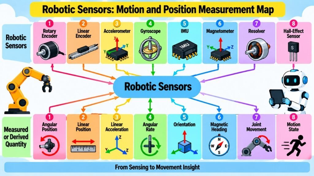
Motion and Position Sensors are Robotic Sensors that measure how a robot moves, where it is positioned, and how it is oriented. These measurements underpin nearly every robotic task involving coordinated movement, and their quality directly determines how precisely motion can be characterized.
Rotary encoders are among the most commonly used position sensors in robotics. They measure angular displacement by counting pulses from a patterned disc or by reading magnetic or optical patterns on a rotating element. Incremental encoders track changes from a defined starting point. Absolute encoders produce a unique output for every angular position across a full rotation, eliminating the need to reference a home position after power-up. Linear encoders apply similar principles to straight-line displacement. Both types offer high resolution but require protection from mechanical shock, debris, and contamination.
Accelerometers measure the acceleration experienced by the sensor, including the gravitational component. They rely on the deformation of a small mechanical structure under inertial forces, which alters an electrical property readable as an output signal. Gyroscopes measure angular velocity, typically exploiting the Coriolis effect in micro-electromechanical systems. Combining both into an inertial measurement unit provides estimates of linear acceleration, angular velocity, and orientation. Accumulated bias in both sensor types integrates over time into growing positional error, a phenomenon known as drift.
Magnetometers measure the local magnetic field direction and intensity. Alongside accelerometers and gyroscopes, they help correct heading drift because the Earth’s field provides an absolute orientation reference. However, nearby ferromagnetic structures or electromagnetic devices distort the local field and can degrade heading accuracy. Selecting motion and position sensors requires weighing resolution, accuracy, repeatability, sampling rate, vibration sensitivity, and the tendency to accumulate error against the demands of the specific application.
Table 4: Robotic Sensors — Motion and Position Sensing Technologies and Measured Quantity
| Sensor Type | Measured Quantity |
| Incremental rotary encoder | Change in angular position from a reference point |
| Absolute rotary encoder | Angular position within a full rotation, uniquely at every point |
| Linear encoder | Straight-line displacement along a defined axis |
| Accelerometer | Linear acceleration including the gravitational component |
| Gyroscope (MEMS) | Angular velocity around one or more axes |
| Inertial measurement unit | Combined angular velocity and linear acceleration across three axes |
| Magnetometer | Direction and intensity of the local magnetic field |
| Resolver | Absolute angular position using electromagnetic induction principles |
4. Robotic Sensors: Force and Tactile Sensors
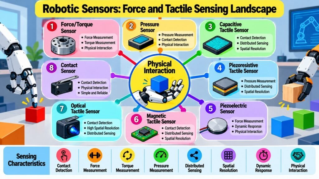
Force and Tactile Sensors are Robotic Sensors that measure physical interaction. Where most sensor categories detect the environment at a distance, force and tactile sensors engage with it directly. They provide information about what a robot is doing to the world, or what the world is doing to the robot, through quantities that arise only through contact.
Force and torque sensors typically measure components of a force vector and a torque vector acting on a deformable mechanical structure. Many designs use strain gauges bonded to a flexure, such as a beam or cross-shaped element. Applied force causes slight deformation, which alters the electrical resistance of the gauges in proportion to the strain. Six-axis sensors simultaneously measure force in three linear directions and torque around three axes, providing complete information about the mechanical interaction at a contact point.
Pressure sensors measure distributed force per unit area across a surface rather than total force at a point. Tactile arrays extend this concept to a grid of independent sensing elements, each recording contact pressure separately. This allows a robot to determine not only that contact has occurred but also where and with what distribution. High-resolution arrays can detect object edges or surface texture. Contact sensors represent the simplest end of the tactile sensing spectrum: they detect only whether contact is occurring, with no information about magnitude. Despite that simplicity, they are reliable, low-cost, and sufficient for many applications.
Key evaluation criteria for force and tactile sensors include sensitivity, measurement range, resolution, hysteresis, and repeatability. Durability matters particularly for these sensors because they experience repeated direct mechanical contact over the sensor’s service life, which can cause wear or gradual calibration shifts that degrade measurement accuracy over time.
Table 5: Robotic Sensors — Force and Tactile Sensing Technologies and Detection Principle
| Sensor Type | Detection Principle |
| Strain-gauge force sensor | Resistance change in deformed gauge bonded to a flexure element |
| Six-axis force/torque sensor | Resolves three force components and three torque components simultaneously |
| Piezoelectric force sensor | Generates charge proportional to applied force via piezoelectric crystals |
| Capacitive tactile array | Detects pressure distribution through capacitance changes between cell pairs |
| Piezoresistive pressure sensor | Resistance varies with applied pressure in a conductive sensing layer |
| Optical tactile sensor | Measures surface deformation by tracking light patterns in a soft medium |
| Contact (limit) switch | Binary detection of physical contact via mechanical switching action |
| Barometric pressure sensor | Measures absolute air pressure for altitude-related robotic applications |
5. Robotic Sensors: Environmental Sensors
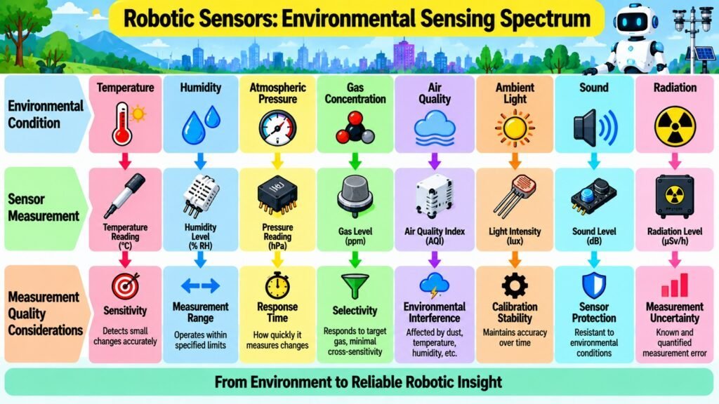
Environmental Sensors are Robotic Sensors that measure the physical, atmospheric, chemical, or acoustic conditions surrounding a robot rather than detecting the properties of specific objects. They give robots awareness of the medium in which they operate, which can affect both the task being performed and the behavior of other sensors in the system.
Temperature sensors measure the thermal state of the environment using principles such as resistance variation or thermoelectric voltage. Thermistors and resistance temperature detectors change their resistance predictably with temperature. Thermocouples generate a voltage at the junction of two dissimilar metals when a temperature gradient exists across that junction. Each technology differs in measurement range, accuracy, and response time, and each is better suited to particular installation conditions and temperature regimes.
Humidity sensors quantify the aqueous vapor concentration present in ambient air. Capacitive implementations are extensively employed and assess the manner in which the dielectric constant of a moisture-absorbing polymer fluctuates upon moisture absorption or release. Atmospheric pressure sensors utilize deformable membranes incorporating strain-sensitive components to determine the absolute pressure of the adjacent gaseous environment. Gas and air quality sensors identify particular chemical substances, encompassing carbon dioxide, carbon monoxide, volatile organic compounds, and particulate matter.
Electrochemical sensors produce a current magnitude proportional to the concentration of the target gas. Metal oxide sensors exhibit resistance variations in response to specific gases when operating at elevated temperatures. Both methodologies demonstrate restricted selectivity and are susceptible to performance degradation over extended operational periods.
Acoustic sensors measure pressure fluctuations in air or other media, while ambient light sensors respond to the intensity of visible or infrared illumination. A recurring theme across environmental sensing is that the conditions being measured can simultaneously influence the sensor doing the measuring. Temperature and humidity affect the performance of other sensors, gas cross-sensitivity complicates air quality readings, and varying illumination alters vision sensor exposure. Recognizing these dependencies is part of using environmental sensors effectively.
Table 6: Robotic Sensors — Environmental Sensor Categories and Measurable Condition
| Environmental Sensor Category | Measurable Condition |
| Temperature sensor | Thermal state of the surrounding environment or a specific surface |
| Humidity sensor | Water vapor concentration relative to saturation level in the air |
| Atmospheric pressure sensor | Absolute gas pressure of the surrounding atmosphere |
| Gas concentration sensor | Presence and level of specific gaseous chemical compounds |
| Air quality / particulate sensor | Concentration of fine particulates or pollutants in the air |
| Acoustic / microphone | Sound pressure fluctuations and acoustic events in the environment |
| Ambient light sensor | Intensity of visible or infrared illumination in the surrounding space |
| Soil moisture sensor | Volumetric water content in soil for ground-engaged robotic applications |
6. Robotic Sensors: Proximity and Presence Sensors
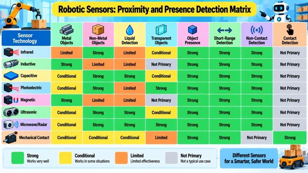
Proximity and Presence Sensors are Robotic Sensors designed to detect whether a target is within a defined sensing zone rather than to measure its precise distance. Many robotic applications require only a threshold response. The relevant question is not how far, but whether something is present, and that simpler question requires less sensor complexity and less computational overhead than full range measurement.
Infrared proximity sensors emit infrared radiation and detect the amount reflected back. Signal strength depends on both target distance and surface reflectivity. A dark surface at short range may produce a weaker signal than a bright surface at longer range, which introduces ambiguity when reflectivity varies across different targets. Capacitive proximity sensors detect changes in the local electric field caused by any dielectric or conductive target, including plastics, liquids, and biological tissue. This makes them useful when metallic targets cannot be assumed.
Inductive proximity sensors detect only metallic targets by measuring changes in an electromagnetic coil’s inductance when a conductive object enters its field. They are inherently unaffected by dust, oil, or non-metallic contaminants, which suits them to demanding industrial environments. Magnetic proximity sensors, including Hall-effect sensors and reed switches, detect the presence of a magnetic field. Attaching a small permanent magnet to a moving mechanical component allows the sensor to register its position as it passes. Photoelectric sensors use a directed light beam, either across a gap to a receiver or reflected from a retro-reflective target. An object that interrupts or blocks the beam causes a detectable state change.
Target material, sensing range, environmental conditions, and installation constraints all determine which proximity technology is appropriate. Electromagnetic interference, vibration, humidity, and temperature degrade reliability in different ways for different sensor types. Understanding the operating principle of each technology is essential for predicting real-world behavior rather than relying solely on specifications established under ideal conditions.
Table 7: Robotic Sensors — Proximity and Presence Sensor Technologies and Detection Principle
| Proximity Sensor Type | Detection Principle |
| Infrared reflective sensor | Detects returned infrared light reflected from a nearby surface |
| Capacitive proximity sensor | Senses changes in local electric field caused by any dielectric target |
| Inductive proximity sensor | Detects inductance change caused by metallic targets entering the field |
| Magnetic reed switch | Mechanically closes a contact in the presence of a magnetic field |
| Hall-effect sensor | Produces a voltage proportional to the strength of a local magnetic field |
| Through-beam photoelectric | Detects interruption of a light beam between an emitter and receiver |
| Retroreflective photoelectric | Detects loss of beam from a retro-reflector when a target intervenes |
| Ultrasonic proximity sensor | Detects nearby objects using the echo return of emitted sound pulses |
7. Robotic Sensors: Sensor Calibration and Accuracy
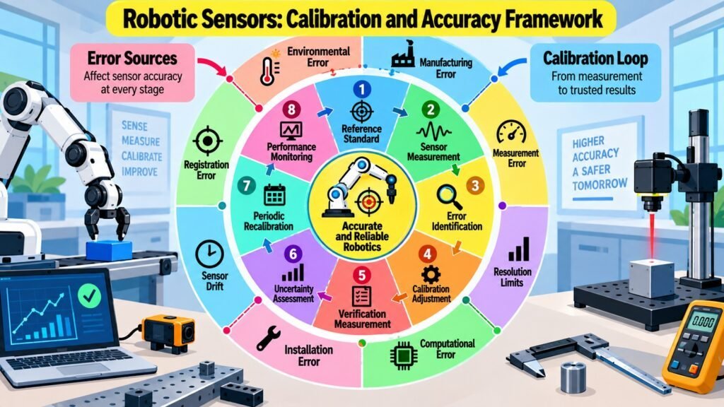
Sensor Calibration and Accuracy represent the measurement-quality dimension of Robotic Sensors. A sensor’s value is not determined solely by what physical quantity it can detect. It depends equally on how faithfully its output represents the true value of that quantity. Two sensors measuring the same phenomenon can produce very different results, and the differences may not be apparent until compared against a reliable reference.
Accuracy describes how close a sensor’s reading is to the true value. Precision describes the repeatability of measurements, meaning how close successive readings are to each other under the same conditions. A sensor can be precise without being accurate if it consistently returns the same incorrect value. Resolution refers to the smallest change in the measured quantity that produces a detectable change in the output. High resolution does not imply accuracy; it only means fine changes can be detected, not that those detected values are correct.
Bias is a consistent offset between a sensor’s readings and the true value, detectable and correctable through calibration. Noise is random variation in output that occurs even when the measured quantity is constant. Drift is a gradual shift in output over time caused by aging, temperature change, or physical wear. Unlike bias, drift is not constant, so a fixed calibration adjustment cannot fully correct for it. Repeatability describes whether the sensor returns the same output for the same input across multiple trials.
Calibration compares a sensor’s output against a known reference and quantifies or corrects the relationship between them. Factory calibration establishes initial accuracy before deployment. Field calibration adjusts for changes arising under actual operating conditions, and periodic recalibration accounts for drift over time. Measurement uncertainty quantifies the range of plausible true values around any reported reading, and recognizing that uncertainty is essential for judging when sensor data can be trusted and when it warrants caution.
Table 8: Robotic Sensors — Key Calibration and Measurement Quality Concepts
| Concept | Meaning or Characteristic |
| Accuracy | Closeness of a sensor reading to the true value of the measured quantity |
| Precision | Consistency of repeated readings under the same measurement conditions |
| Resolution | Smallest detectable change in the measured quantity at the sensor output |
| Bias (systematic error) | Consistent, repeatable offset between sensor readings and true values |
| Noise | Random variation in sensor output unrelated to actual changes in the quantity |
| Drift | Gradual shift in sensor output over time due to aging, temperature, or wear |
| Repeatability | Ability to return the same output for the same input across multiple trials |
| Measurement uncertainty | Quantified range within which the true measurement value is expected to fall |
8. Robotic Sensors: Sensor Fusion and Integration
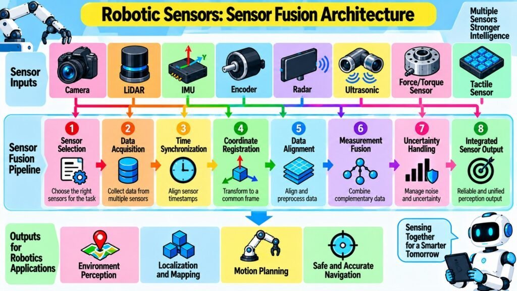
Sensor Fusion and Integration represent the system-level culmination of Robotic Sensors. Individual sensors are constrained by their operating principles, their accuracy, and the conditions they can tolerate. Combining multiple sensors allows a robotic system to compensate for those individual limitations, obtain more complete information, and maintain reliable operation in situations where any single sensor would fail or degrade.
Sensor integration is the process of incorporating multiple sensors so their outputs are all available. Sensor fusion is the computational process of combining those outputs into an estimate more accurate, complete, or robust than any individual sensor could produce alone. Integration is primarily a hardware and architectural concern; fusion is a data-processing concern. Both are necessary for a multi-sensor system to be effective.
Spatial and temporal alignment are prerequisites for fusion. Different sensors are mounted at different positions and orientations, so their outputs are expressed in different coordinate frames. Transforming all outputs into a common frame is required before any meaningful combination. Temporal alignment matters equally, since sensors sample at different rates and carry different internal processing delays. Associating measurements that relate to the same physical event requires careful synchronization.
Complementary sensing is one of the most useful principles in fusion. An accelerometer and a gyroscope are complementary: the accelerometer gives accurate estimates at low frequencies but is noisy at high frequencies, while the gyroscope is accurate at high frequencies but drifts at low frequencies. A complementary filter or Kalman filter exploits the strengths of each while suppressing the weaknesses. The Kalman filter models sensor noise explicitly, weighting each sensor’s contribution according to its estimated reliability at each moment.
Key challenges include conflicting measurements when sensors disagree, cumulative error as small inaccuracies integrate over time, and the added system complexity that multi-sensor designs require. When sensors are combined thoughtfully, the result is a robotic system with broader sensing coverage, higher reliability, and more graceful degradation when individual sensors are impaired.
Table 9: Robotic Sensors — Sensor Fusion Concepts and Their Role in Integration
| Fusion Concept | Role in Sensor Integration |
| Sensor integration | Incorporating multiple sensors so their outputs are available to the system |
| Coordinate frame transformation | Converting each sensor’s output into a shared spatial reference |
| Temporal synchronization | Aligning measurements from sensors with different sampling rates or delays |
| Complementary filtering | Combining sensors that perform well in different frequency ranges |
| Kalman filtering | Statistically weighted fusion using explicit models of sensor noise and uncertainty |
| Redundancy | Using multiple sensors for the same quantity to detect failures and improve reliability |
| Bayesian estimation | Probabilistic framework for updating measurement estimates as new data arrives |
| Measurement conflict resolution | Handling sensor disagreements through weighting or outlier rejection |
Conclusion: Robotic Sensors and the Future of Robot Sensing
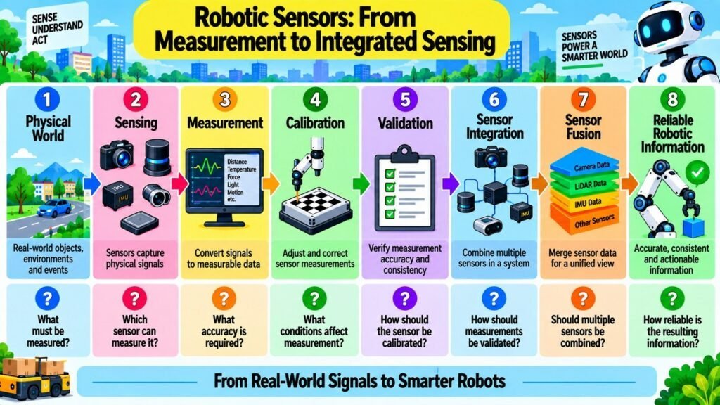
The eight aspects covered in this article form a coherent framework for understanding Robotic Sensors as both a technical and conceptual subject. Vision, range, motion, force, environmental, and proximity sensors each address a distinct category of physical measurement. Calibration and accuracy establish the quality foundation that determines whether those measurements are dependable. Sensor fusion and integration show how individual technologies combine to produce information more complete and reliable than any single sensor could offer.
A central lesson running through all eight sections is that selecting a Robotic Sensor is not simply a matter of choosing the most advanced technology or the highest specification. What matters is the match between the sensor and task. That match depends on what physical quantity needs to be detected, with what accuracy and resolution, under what conditions, and with what level of reliability. A sensor that performs well in one setting may degrade significantly in another, and its measurements are only as trustworthy as the calibration that backs them up.
The trajectory of Robotic Sensors points toward greater capability in smaller form factors, improved robustness under demanding conditions, tighter integration between multiple sensing modalities, and higher measurement quality at lower cost. Developments in miniaturization, materials science, and signal processing continue to expand what is achievable. Multimodal sensing, combining several measurement principles in a single compact unit, is increasingly practical rather than aspirational.
What remains constant across technological generations is the fundamental logic of sensing. Physical phenomena must be transduced into signals. Those signals must be accurate, consistent, and well characterized. Limitations must be understood, not overlooked. Where individual sensors fall short, thoughtful integration and fusion can compensate. Grasping Robotic Sensors at this level is not incidental to understanding modern robotics — it is foundational to it.
Table 10: Robotic Sensors — Summary of the Eight Foundational Aspects and Their Role
| Robotic Sensors Aspects | Role in the Robotic Sensor Framework |
| Vision Sensors | Convert visual phenomena into structured image or depth data |
| Distance and Range Sensors | Measure spatial separation to environmental features and objects |
| Motion and Position Sensors | Quantify displacement, orientation, velocity, and acceleration |
| Force and Tactile Sensors | Detect physical interaction forces, torques, pressure, and contact |
| Environmental Sensors | Measure atmospheric, thermal, chemical, and acoustic conditions |
| Proximity and Presence Sensors | Detect whether a target is within a defined detection zone |
| Sensor Calibration and Accuracy | Establish and maintain measurement quality over time |
| Sensor Fusion and Integration | Combine multiple sensing outputs for more complete, reliable data |